Blinking_Light

ZedBoard Blinking Light by vivado

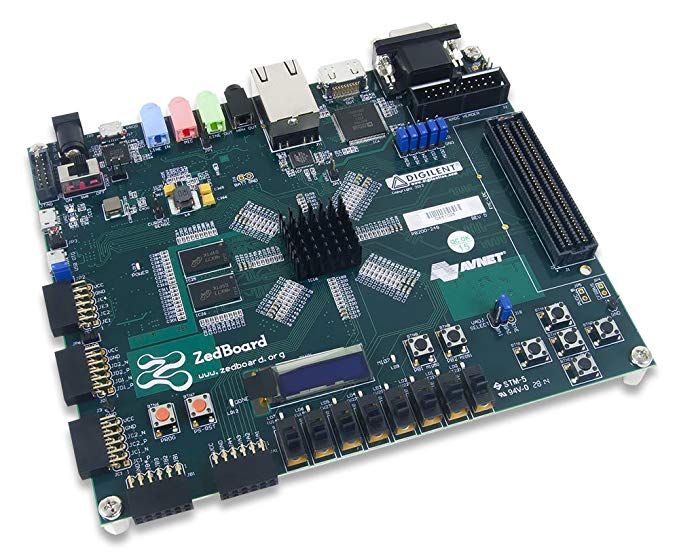
ZedBoard™ is a complete development kit for designers interested in exploring designs using the Xilinx Zynq®-7000 All Programmable SoC. The board contains all the necessary interfaces and supporting functions to enable a wide range of applications. The expandability features of the board make it ideal for rapid prototyping and proof-of-concept development.
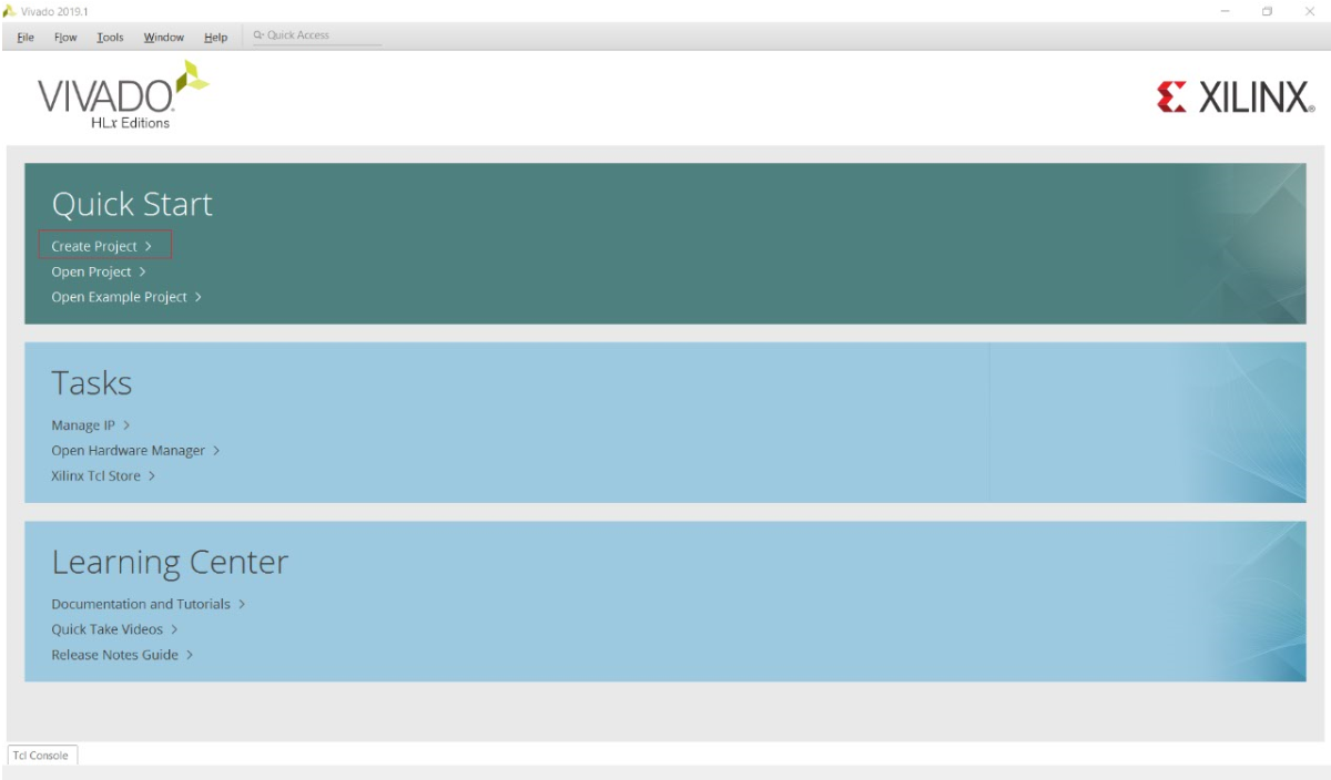
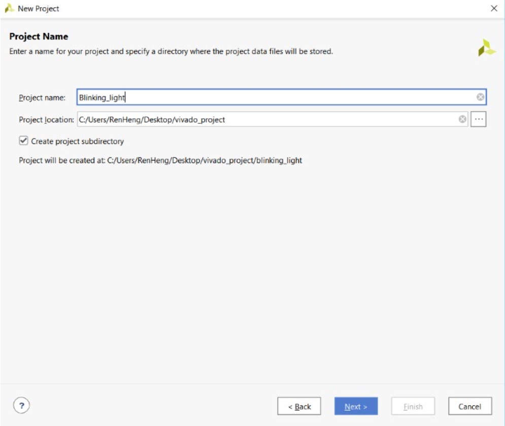

1、Create Project


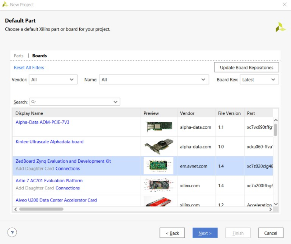
Project Name -> RTL Project -> Next -> Choose “Boards / ZedBoard Zynq Evaluation and Development Kit”-> Finish
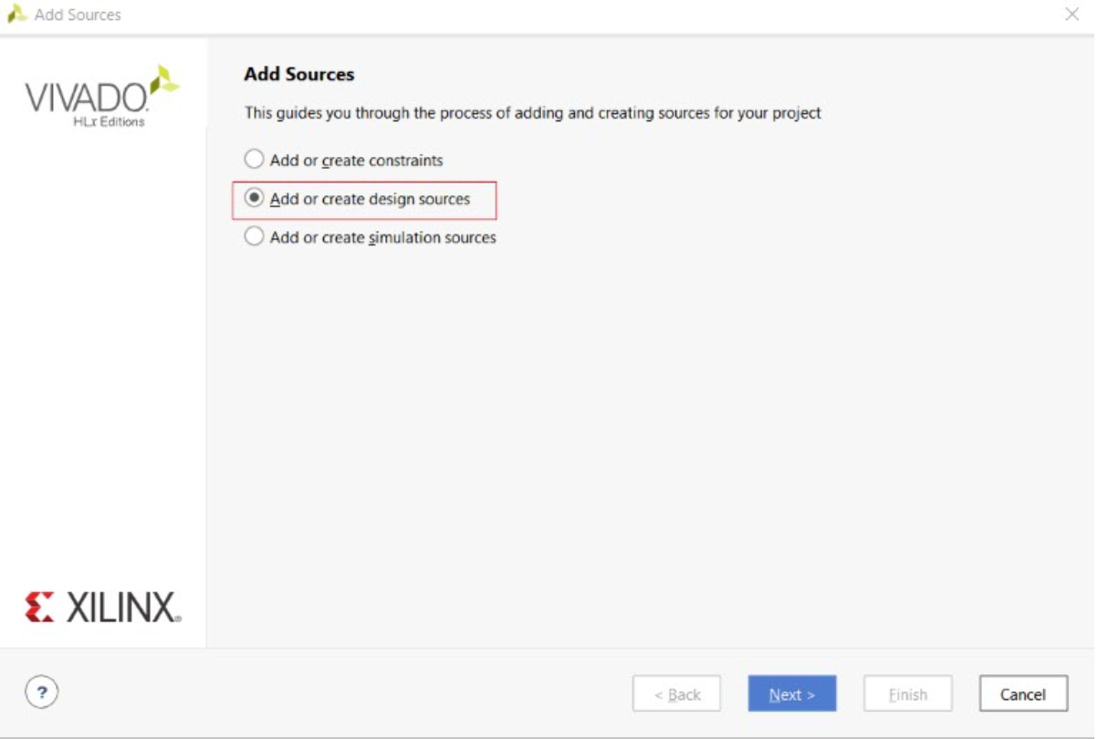
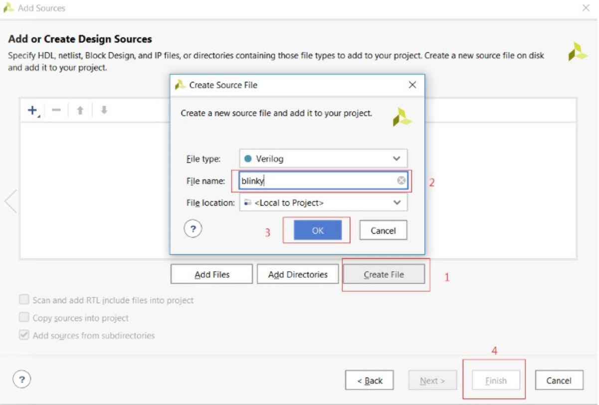

2、Module blinky.v


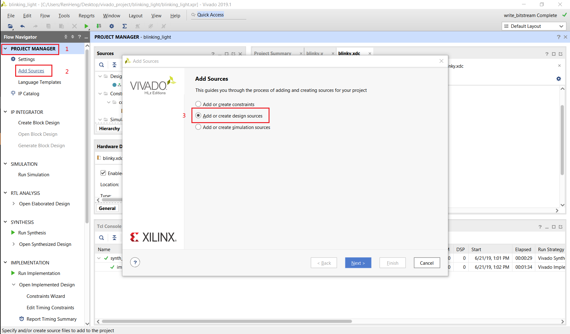
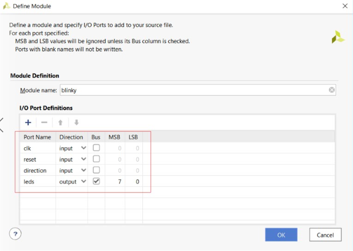
Add Sources -> module name -> set I/O port


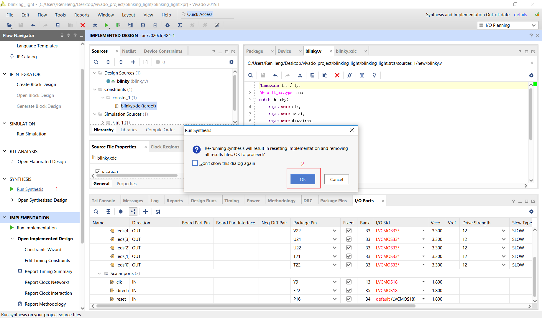
Edit blinky.v -> Run Synthesis -> Run Implementation -> Open Implementation Design

1
2
3
4
5
6
7
8
9
10
11
12
13
14
15
16
17
18
19
20
21
22
23
`timescale 1ns / 1ps
`default_nettype none
module blinky(
input wire clk,
input wire reset,
input wire direction,
output reg [7:0] leds
);

always@(posedge clk)begin
if(reset == 1)begin
leds <= 1;
end
else begin
if(direction == 1)begin
leds <= { leds[6:0], leds[7] };
end
else begin
leds <= { leds[0], leds[6:1] };
end
end
end
endmodule

We can get ZedBoard Ports and some details by Download ZedBoard Hardware User’s Guide

We can get ZedBoard Ports setting .ufc by Download Zedboard Master UCF Rev C/D v3

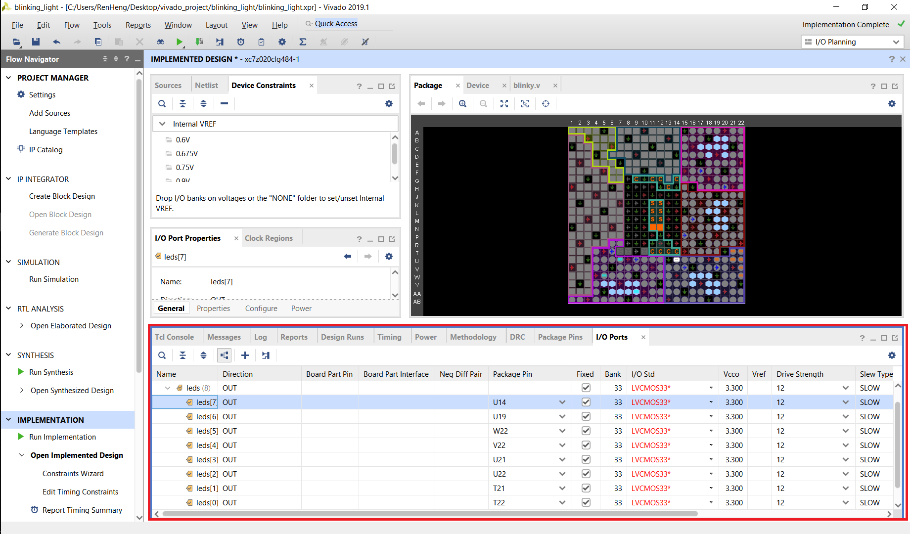
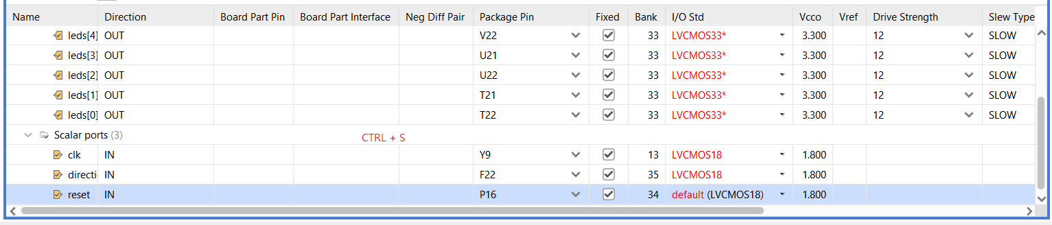
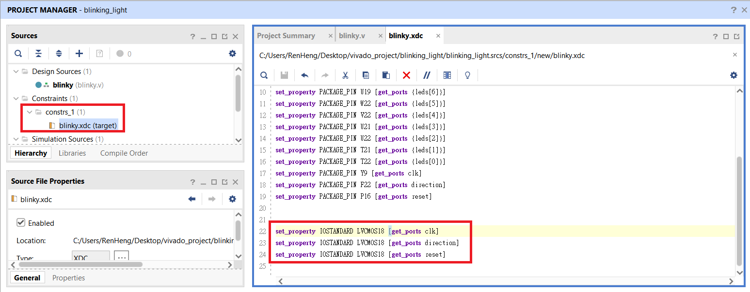
Then we know LED ports are : U14、U19、W22、V22、U21、U22、T21、T22

Now , your leds are lighting


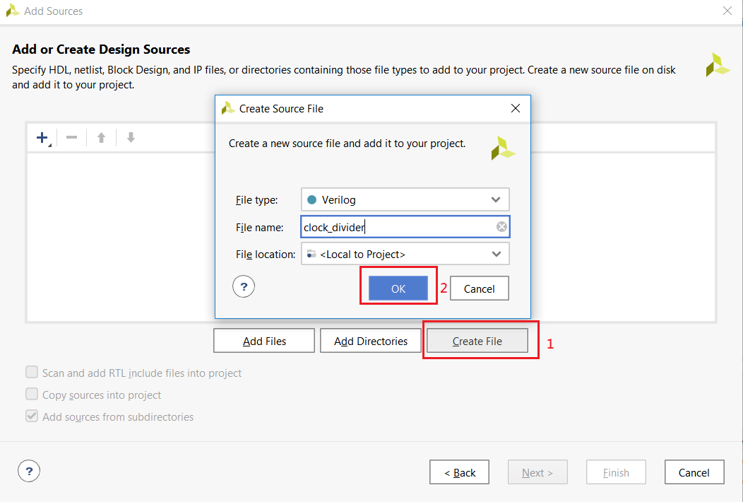
3、Module clock_divider.v

Edit clock_divider.v

1
2
3
4
5
6
7
8
9
10
11
12
13
14
15
16
17
18
19
20
21
22
23
24
25
26
27
`timescale 1ns / 1ps
`default_nettype none
module clock_divider(
input wire clk_in,
output reg clk_out
);

parameter DIVIDER = 10000;
reg [$clog2(DIVIDER)-1:0] count = 0;
reg reset = 1;
always @(posedge clk_in)begin
if(reset == 1)begin
reset <= 0;
clk_out <= 0;
count <= 0;
end
else begin
if(count == DIVIDER)begin
clk_out <= ~clk_out;
count <= 0;
end
else begin
count <= count + 1;
end
end
end
endmodule

Edit blinky.v

1
2
3
4
5
6
7
8
9
10
11
12
13
14
15
16
17
18
19
20
21
22
23
24
`timescale 1ns / 1ps
`default_nettype none
module blinky(
input wire clk,
input wire reset,
input wire direction,
output reg [7:0] leds
);
wire divclk;
clock_divider #(.DIVIDER(50_000_000)) div( .clk_in(clk), .clk_out(divclk));
always@(posedge divclk)begin
if(reset == 1)begin
leds <= 1;
end
else begin
if(direction == 1)begin
leds <= { leds[6:0], leds[7] };
end
else begin
leds <= { leds[0], leds[6:1] };
end
end
end
endmodule

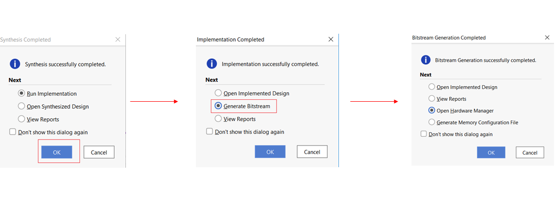
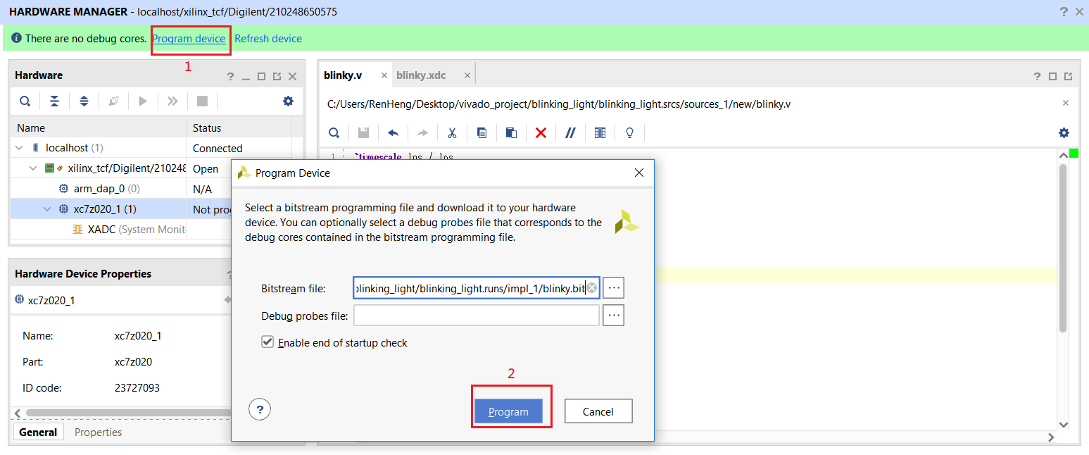
Edit clock_divider.v -> Edit blinky.v -> Run Synthesis -> Run Implementation -> Generate Bitstream ->
Open hardware Manager -> Program again

Now , we can choose shift_right or shift_left by switch


Reference

First project with Vivado